Pre-Flight Testing
In order to help troubleshoot any issues after installation, it’s important to get a baseline of the game before you start. The cross rising mod relies on the LED flasher that is inside the cross and the last grave drop down target to determine when to rise. Go into the game test menu and verify both are working before attempting to install the mod.
LED Cross Flasher
-
- In the service menu, select: DIAG -> FLASH LAMP MENU-> SINGLE FLASH LAMP TEST -> GRAVE MARKER L.E.D. FLASHER #19, ORG / VIO-ORG
- With the coin door closed, press the start button to activate the flasher. If the cross doesn’t flash, it will need to be fixed before continuing. Possible causes may be a dead bulb, a bad wiring harness (most likely on the cross side), or a bad Q19 transistor.
- If the LED needs to be replaced, be aware it is a 12v wedge type flasher LED. NOT a standard 6v GI LED.
Grave Drop Target
-
-
- In the service menu, select: DIAG -> SWITCH MENU -> SWITCH TEST
- With the playfield up, manually drop the targets from below. Verify that the last target switch changes state when it is dropped and raised back up again. You won’t be able to see the DMD, but you will hear the sound that indicates a change in switch state. Again, if it doesn’t test as expected, this will need to be resolved before continuing with the mod.
-
Cross Mod Install
POWER OFF THE GAME BEFORE PROCEEDING!
1) Remove the factory cross mount from the playfield
- There are three screws under the PF to hold the factory mount. You will reuse two of these screws.
- Unplug the cross LED. You won’t need to reuse the harness Z-adapter.
- Pull the cross and mount out of the playfield.
2) Remove the cross from the factory mount
- Three screws hold the cross to the mount, take those out. You won’t reuse these screws
3) Mount the cross to the new mech
- Use the included low profile screws and mount the cross. Make sure the screws are flush with the new mount. It is expected the cross has #6-32 threaded inserts as it came from the factory.
4) Route the cross LED harness
- Route the cross LED wire through the groove in the arm post and secure with a zip tie (not included) run through the slot in the post. It does not need to be tight, just enough to keep the wire from coming out of the groove. This is to make sure the wires don’t get in the way of the servo arm. Be mindful to rotate the buckle of the zip tie to be on the side of the post so it doesn’t interfere with the playfield cutout when the cross rises.
5) Install the new cross mech
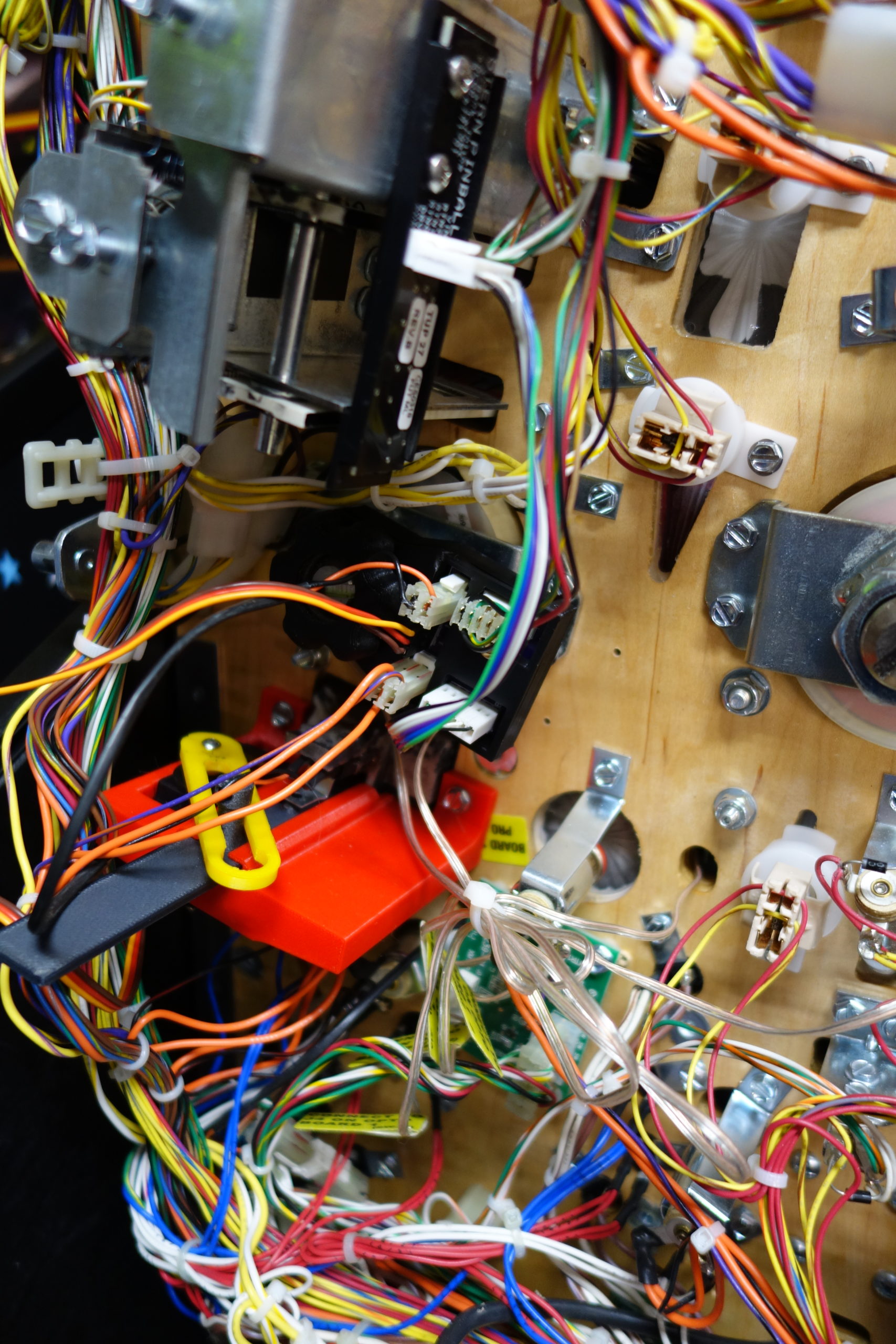
- Slide the cross up through the PF. Use the two screws from step 1 and mount the new mount. Only the outside holes are used. They should go back in the original holes. NOTE: You will need to loosen and rotate the factory wire management tower to get the mech to fit. You may need to cut the main harness zip ties from the tower and re-secure or relocate the tower to make it all fit.
6) Mount the cross PCB
- Fit the PCB over the cross magnet hex bolt. Use the included wheel nut to secure the PCB.
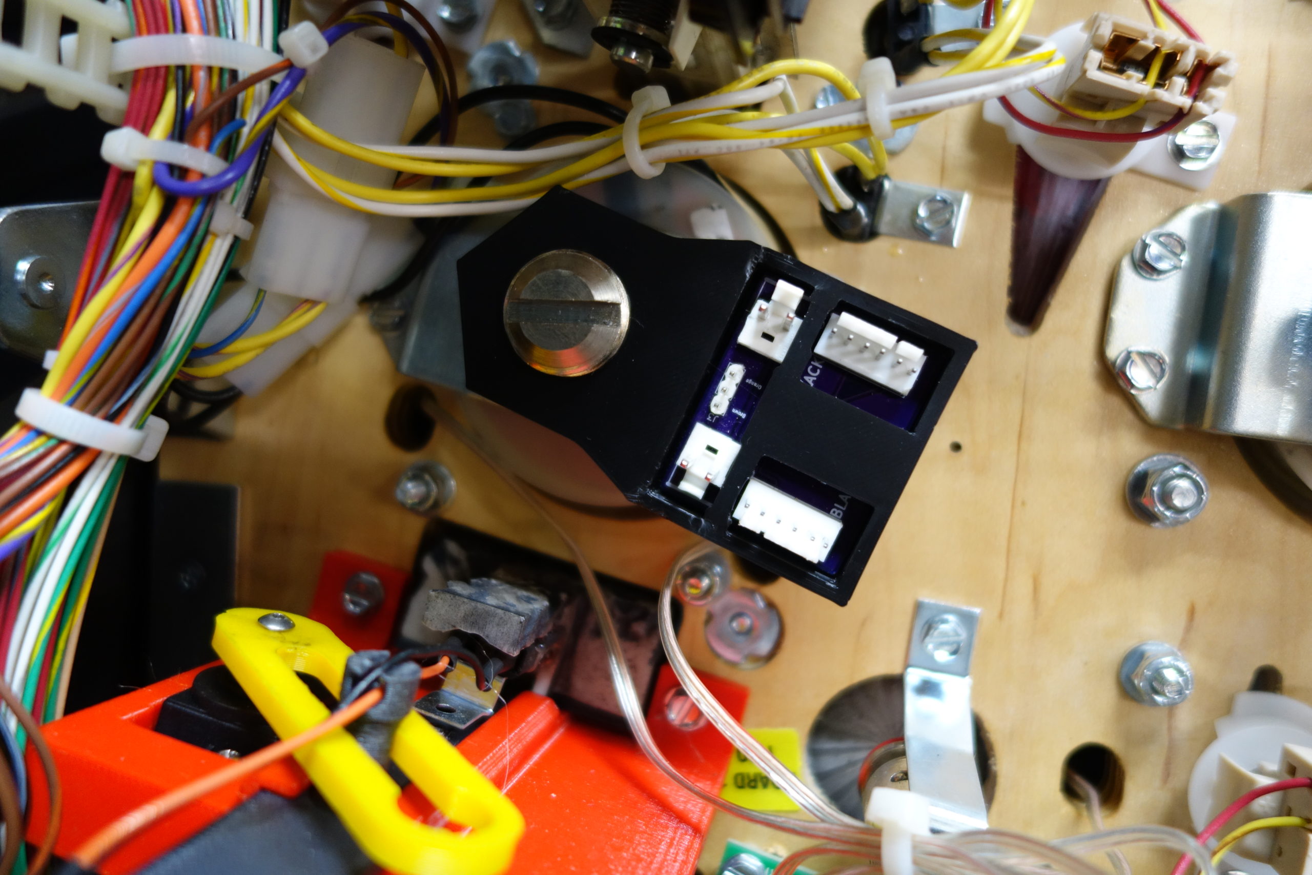
**It is important that you get the orientation of the plugs correct in the next few steps. Use the reference pictures to double check you get this right**
7) Cross mod PCB to drop target opto board harness
- Note the orientation of the plug on the drop target opto board. Use the black wire as reference. Unplug the game harness from the drop target opto board.
- Connect the included patch harness to the rising cross PCB. Use the connector header closest drop targets and note the orientation of the black wire. Use the below wired picture for reference. There is also texted on the PCB (somewhat obscured under the plastic housing) that indicates which side the black wire should connect. Now connect the other end to the drop target opto board. Make sure to orientate the black wire as original. It should be with the black wire side closest to you (opposite side of PF).
- Plug the original opto board connector to the rising cross PCB. It is likely that you will need to cut some factory harness zip ties in order to have enough slack to reach the new PCB. Again, pay attention to the orientation of the plug using the black wire as reference. If you look close at the PCB, you should see a note that says “BLACK”. It’s kind of hard to see with the plastic housing. Also the connector locking ramps should prevent getting this backwards, but it is always good to double check.
8) Cross LED harness
- The cross LED harness was separated in step 1. Plug the game side part of the harness to the two-pin connector on the right side of the new PCB. Use the locking tab to get the correct orientation with the pin header. NOTE: It is likely you will need to cut zip ties on the game harness to get enough slack.
- Plug the cross side plug for the cross LED to the left side two pin connector. Again, use the lock tab to get the orientation correct.
9) Servo connection
- Connect the servo plug to the cross PCB. The plug orientation is the brown wire will be on the left. This connector can be plugged in backwards.
Post Install Testing
After double checking all connections, turn the game power on with the playfield still up. The servo is programmed to jump to the middle position, slowing move to fully raised, then slowly reset back to fully down (earlier versions would not go full up). If the cross does not move, immediately power-off and review each connection. If no fault is found, reach out to me for troubleshooting support. If the cross moves as expected, watch closely to make sure that there is no interference with the PF cutout or any wires. Also verify that the cross LED harness has enough slack during full extension. If there are any impediments to cross movement, immediately power-off the game and adjust as necessary. Any restriction to servo movement could cause damage to the servo or other electronics.
After confirming the cross initializes and moves freely, run through the Pre-Flight tests one final time. If either the target opto switches or flasher tests fail, inspect all of the connectors for loose wires or connector pins.
If the tests pass, it’s ready for gameplay. Enjoy the mod!